
Precision CNC Actuator Housings for Robotics
RobotPartsCNC provides precision CNC machining services for robotic actuator housings, gearbox casings, and motor mounts. We convert complex CAD designs into reliable hardware with accurate bearing interfaces, precision hole patterns, and controlled GD&T.
From collaborative robot joints and humanoid actuators to high-torque gearboxes, our engineering team supports the path from prototype validation to repeatable production.
±0.01 mm
Standard tolerance
±0.005 mm
Critical interfaces
3–7 days
Prototype lead time
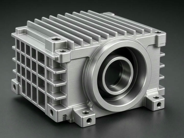
Built around critical interfaces
Motor, reducer, bearing, flange, and precision hole-system requirements are reviewed as one integrated assembly.
Engineering focus
Designed for alignment, stiffness, and repeatability
Actuator housings form the structural foundation for the motor, harmonic or planetary gear set, and output bearings. Small deviations can affect vibration, backlash, wear, and robot positioning performance.
Discuss your housing designPrecision bearing fits
Bearing bores are managed for the required interference or clearance fit to help prevent vibration and premature wear.
Thin-wall machining
Machining strategies help minimize chatter and distortion across lightweight walls, ribs, and structural sections.
Coaxiality and alignment
Five-axis machining and multi-setup planning support alignment between the motor shaft, gearbox, output flange, and mounting features.
Complex internal cavities
Specialized tooling and multi-axis milling reach deep pockets and internal mounting surfaces while protecting surface finish.
CNC capability
Five-axis capability for integrated actuator interfaces
Our 3-axis, 4-axis, and 5-axis CNC equipment supports housing geometries that combine motor mounts, reducer interfaces, bearing seats, flange patterns, and internal cavities.
5-axis machining
Complex geometryMachine features on multiple sides in fewer setups to improve positional accuracy and reduce lead times.
Mill-turn machining
Concentric featuresCombined turning and milling centers support cylindrical housings, shafts, diameters, and flange mounting holes.
Tolerance control
Critical fitsStandard tolerance is ±0.01 mm, with capability to hold ±0.005 mm for critical bearing seats and pilot diameters.
DFM review before production
Our engineering team reviews every CAD model for inaccessible cavities, radius constraints, and tolerances that may add cost without functional benefit. We then optimize the machining strategy around your robot's performance requirements.
Material and finish selection
Match strength, weight, and environment
Material selection is guided by the required strength-to-weight ratio, load profile, wear conditions, and operating environment.
Aluminum: 6061-T6 and 7075-T6
Lightweight, high-strength options for actuator housings; 7075-T6 suits high-load applications where weight is a primary constraint.
Stainless steel: 303, 304, 316, and 17-4PH
Selected for corrosion resistance, medical-grade cleanliness, or higher hardness and wear resistance.
Carbon and alloy steel: 4140 and 4340
Used for structural components requiring higher tensile strength and fatigue resistance.
Secondary treatments
Protect critical surfaces
- Hard anodizing for improved wear resistance on aluminum components.
- Electroless nickel plating for precision surfaces and protection.
- Passivation for stainless steel components.
Quality assurance
Inspection built around robot-joint geometry
Every production run is verified against your drawings and technical specifications to support reliable assembly and repeatable robot performance.
Coordinate measuring machine
Verify complex geometries, true position, and hole patterns.
Geometric tolerancing
Monitor flatness, parallelism, perpendicularity, and runout.
Precision gauging
Use bore gauges, air gauges, and plug gauges for fits and internal diameters.
Traceable documentation
Receive FAI reports, dimensional inspection reports, and material certificates.
Production path
From prototype to production volume
Validate fit, form, and function
Fast-turnaround machining supports engineering prototypes during the R&D phase. Prototype lead times range from 3–7 working days.
Scale with process consistency
After design validation, we optimize fixtures, batch inspection protocols, and material sourcing for orders from 50 to 10,000+ pieces.
Ready for engineering review?
Send your actuator housing requirements
We accept STEP, STP, IGES, X_T, and PDF files. Share your CAD data, drawings, material, finish, quantity, and critical inspection requirements with our engineering team.
Start your quote requestInclude these project details
- ✓3D CAD models and 2D technical drawings
- ✓Material and surface finishing requirements
- ✓Prototype and potential production quantities
- ✓Critical dimensions and inspection requirements
Request a quote
Bring your next actuator design to production
We specialize in precision CNC machining for robotics and automation applications.
Company: RobotPartsCNC
Email: info@robotpartscnc.com
Address:
Technical questions
Actuator housing machining FAQs
What tolerance can you hold on actuator housing features? +
Our standard tolerance is ±0.01 mm, with capability to hold ±0.005 mm for critical bearing seats and pilot diameters, subject to the feature, material, and inspection requirements.
Which files should be submitted for a quote? +
Please provide STEP, STP, IGES, X_T, or PDF files, along with 2D drawings where available. Material, finish, quantity, critical dimensions, and inspection requirements help us prepare a complete review.
Can you support both prototypes and production batches? +
Yes. Prototype machining is available with lead times ranging from 3–7 working days, followed by low-volume and production support for orders from 50 to 10,000+ pieces.