
Precision CNC Chassis Components for AMR, AGV and Mobile Robots
RobotPartsCNC converts CAD designs into lightweight, high-rigidity chassis structures and drive-system components with the precise interfaces required for reliable robot assembly.
±0.005 mm
Tight tolerance capability
3–7 days
Prototype lead time
±0.01 mm
Standard tolerance
Ra 0.4–3.2
Surface roughness, μm
1000 mm
Maximum milling length
7–20 days
Production lead time
Built around robot motion
Chassis components engineered for precise interfaces
Mobile robot structures must reduce weight without sacrificing rigidity. We machine the datums, bores, mounting patterns and structural surfaces that keep drive modules, wheel assemblies, sensors and batteries correctly positioned.
Drive and wheel systems
Wheel hubs, drive housings and precision shafts accommodate high-load bearings, controlled rotational tolerances and repeatable wheel interfaces.
Structural frames
Base plates, chassis ribs and mounting brackets are machined for flatness and perpendicularity to support stable robot movement.
Sensor and LiDAR mounts
Precision-machined interfaces for LiDAR, cameras and proximity sensors help maintain the alignment required by navigation software.
Motor and actuator interfaces
Motor mounts and gear-reducer housings are machined with controlled bore tolerances to reduce gear misalignment and vibration.
Manufacturing capability
Complex geometries, controlled in one process
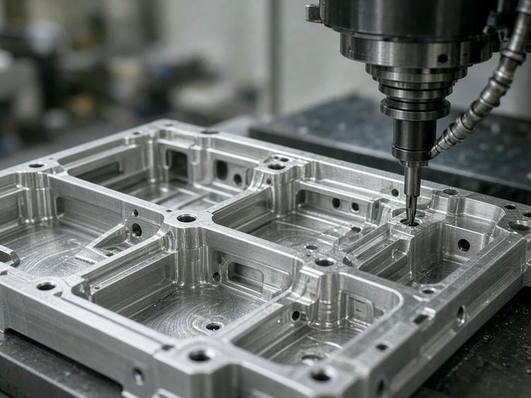
Our Shenzhen facility uses multi-axis CNC milling and turning to produce the lightweight structural parts and circular drive components common to AMR and AGV platforms.
Discuss your component design5-axis machining
Suitable for complex chassis brackets and arm links requiring multiple angles in a single setup, reducing geometric error and improving surface finish.
Mill-turn machining
Combines precision turning with secondary milling for wheel hubs and drive shafts, including bolt patterns and keyways.
Thin-wall machining
Dedicated fixturing and tool-path strategies help prevent warping and chatter in lightweight aluminum housings.
Precision boring
Dedicated setups support bearing bores and press-fit interfaces where interference fits must meet engineering specifications.
Material selection
Balance robot weight, durability and cost
Choose materials according to load, environment, wear requirements and the need for electrical insulation.
Aluminum
6061-T6 and 7075-T6 for chassis plates, brackets and motor mounts. 7075 supports higher-load structural parts.
Stainless steel
303, 304 and 316 for corrosive settings, harsh environments and exposed drive hardware.
Carbon and alloy steel
1018 and 4140 for heavy-duty shafts, drive components and internal gears requiring high tensile strength.
Engineering plastics
POM, PEEK and Nylon for sensor housings, cable interfaces and non-structural parts requiring low weight or insulation.
Engineering support
DFM feedback before production
Our engineering team reviews CAD models and 2D drawings to identify manufacturing risks and protect assembly performance.
GD&T and datums
Clarify critical references for bearing fits, wheel interfaces and sensor alignment.
Tooling access
Review pocket depths and radii to avoid deep-cavity issues that increase cost or lead time.
Surface finish
Recommend hard anodizing, powder coating and other finishes for wear or environmental protection.
Fixture design
Develop custom holding fixtures for irregular chassis parts and repeatable production batches.
Quality assurance
Inspection records for critical interfaces
We verify the dimensions and geometric requirements that affect robot assembly, movement and sensor performance.
- ✓CMM reporting for complex parts with tight true-position requirements.
- ✓Dimensional inspection of bearing bores, thread fits and bolt patterns.
- ✓Surface roughness testing for sliding interfaces and specified finishes.
- ✓Material certificates and lot traceability for production orders.
| Capability | Specification |
|---|---|
| Standard tolerance | ±0.01 mm |
| Tight tolerance | Down to ±0.005 mm |
| Surface roughness | Ra 0.4–3.2 μm |
| Maximum milling size | 1000 × 600 × 600 mm |
| Maximum turning size | Ø400 × 800 mm |
| Prototype lead time | 3–7 working days |
| Production lead time | 7–20 working days |
Project questions
Practical answers for your chassis program
Start your project
Send your chassis files for a technical review
Share your CAD models, material requirements and quantity. Our engineering team will review the design and provide a lead-time and cost estimate.
Required for quote
- 3D CAD models: STEP, STP or X_T
- 2D drawings with tolerance callouts
- Material specifications
- Quantity requirements
- Inspection or certification needs