Precision CNC Machined Sensor & LiDAR Mounts for Robotics
Robotic navigation and perception rely on the precise positioning of LiDAR, depth cameras, and ultrasonic sensors. If your sensor mounts lack structural rigidity or consistent alignment, your software team will struggle to calibrate the data. RobotPartsCNC provides high-precision CNC machining for custom sensor brackets, camera housings, and LiDAR interfaces that keep your hardware calibrated and secure under operational stress.
- Tight Tolerance
- ±0.005 mm
- Standard Tolerance
- ±0.01 mm
- Prototype Lead
- 3–7 days
- DFM Review
- Within 24h
Engineering for Sensor Accuracy
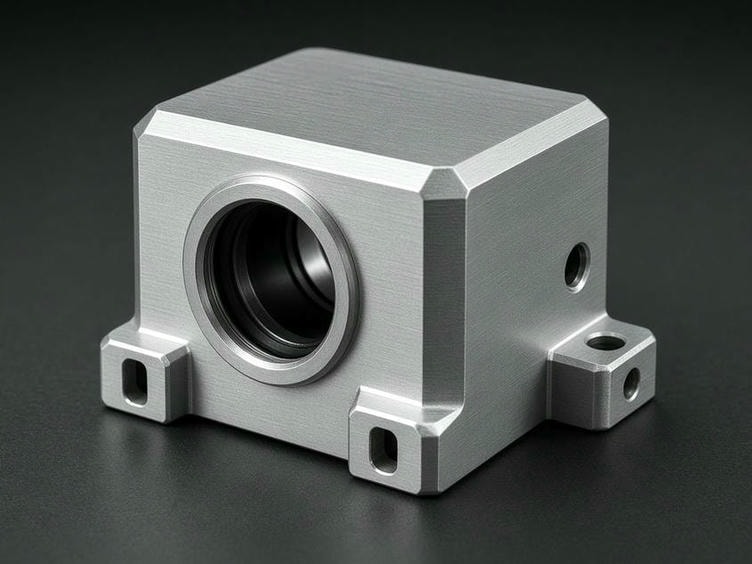
We machine sensor mounts that prioritize mechanical stability and optical alignment. Whether you are building an AMR, a humanoid, or an inspection robot, our engineering team reviews your CAD files to ensure the following.
Geometric Precision
Tight tolerances on mounting interfaces keep LiDAR and camera modules at the exact required pitch, roll, and yaw angles.
Vibration Resistance
Machining processes for aluminum and carbon steel deliver the rigidity needed to prevent sensor jitter, ensuring clean data acquisition even on mobile platforms.
Weight Optimization
Pocketing and thin-wall milling reduce mass on robot arms and heads without compromising the structural integrity of the mount.
Repeatable Locating
Precision bores and dowel pin holes create mounting interfaces that allow removal and re-installation of sensors without time-consuming recalibration.
Manufacturing Capabilities
Our facility in Shenzhen is equipped for the specific needs of sensor integration, from small-batch prototypes to production runs.
| Standard Tolerance | ±0.01 mm |
|---|---|
| Tight Tolerance | Down to ±0.005 mm |
| Max Milling Size | 1000 × 600 × 600 mm |
| Surface Roughness | Ra 0.4–3.2 μm |
| Lead Time (Prototype) | 3–7 working days |
| Lead Time (Production) | 7–20 working days |
| Materials | 6061-T6, 7075-T6, 303/304 Stainless, POM, PEEK |
Optimized for Rapid Integration
Robotics projects move fast. We support your development cycle at every stage, from first prototype to production ramp.
Fast Turnaround
By leveraging our local supply chain in Shenzhen, we deliver prototype mounts in days, not weeks, so your engineering team can validate sensor fields of view and mounting positions in real-world testing sooner.
DFM Feedback
Before we cut metal, we identify features that may cause issues, such as inaccessible screw holes, thin walls prone to vibration, or sharp internal corners. We suggest adjustments to improve part performance while keeping manufacturing costs low.
Secondary Processing
Anodizing for electrical conductivity or insulation, bead blasting for a non-reflective matte finish ideal for optical sensors, and laser marking for sensor orientation identification or serial tracking.
Material Selection for Sensor Hardware
The choice of material impacts both the robot’s power efficiency and the stability of the sensor readings.
6061-T6 Aluminum
The standard for most mounts. An excellent strength-to-weight ratio, easily anodized for corrosion resistance.
7075-T6 Aluminum
Used when high structural strength is required to prevent deflection on long-reach robot arms or high-impact environments.
Stainless Steel (303/304)
Recommended for sensor mounts in medical or harsh environments where chemical resistance or high-temperature stability is critical.
Engineering Plastics (POM/PEEK)
Used for lightweight, non-conductive mounts or when electrical isolation is required between the sensor and the robot chassis.
Quality Control for Precision Assemblies
Sensor mounts are often small but complex. We use CMM (Coordinate Measuring Machine) inspection and optical measuring equipment to verify the critical dimensions of your mounting holes, bearing seats, and alignment surfaces.
- CMM inspection of critical mounting dimensions
- Optical measurement of alignment surfaces and bearing seats
- Full inspection report with every order
You receive a full inspection report with every order, ensuring the parts you receive match the CAD model exactly.
Request a Quote for Your Sensor Mounts
To get started, send your 3D CAD models (STEP/STP/X_T) and 2D drawings to our engineering team. Please include your material specifications, quantity requirements, and any specific surface finish needs.
If you have a complex assembly or need advice on the manufacturability of your sensor bracket design, mention your application (e.g., AMR drive module, humanoid head, or lab automation) when you reach out. We will provide a quote and a DFM review within 24 hours.
info@robotpartscnc.com
Facility
Phone